Installation and alignment between girth gear and pinion of ball mill
There are two kinds of transmission forms of ball mill, i.e. center transmission and edge transmission. The two kinds of transmission have their own advantages and disadvantages. The central transmission adopts a high-speed planetary reducer, which is safe and reliable, with a service life of up to 10 years, low maintenance cost, but large one-time investment.
The cost of edge drive is low, but the pinion needs to be replaced every 2-5 years. Edge drive is mainly used in coal mills and mills with small power.
The girth gear(big ring gear) and pinion are the key of the edge transmission device. Their reliable operation is directly related to the stable production of the mill. In order to ensure their reliable operation, in addition to strengthening the daily maintenance and regular maintenance, the installation and alignment of the girth gear and pinion are also important.
01- installation and alignment of edge drive
The installation and alignment process of edge drive is as follows:
Cleaning of gear ring and mill flange → positioning of gear ring → coarse alignment of large gear ring → positioning and coarse alignment of pinion → installation of motor reducer → primary grouting → fine alignment of large gear ring → fine alignment of pinion → fine alignment of motor reducer.
02- alignment of girth gear (big gear)
In order to reduce the workload of installing gears on site, hobs with similar wear conditions should be selected during finishing of large and small gears, so as to make the meshing profile of large and small gears as close as possible and increase the contact area. Before the gear is installed, the tooth thickness vernier caliper can be used to check the tooth thickness of the gear ring indexing circle chord, or the tooth shape template can be made of sheet steel to retest the tooth shape. If necessary, it needs to be repaired on site.
2.1 ring gear mating surface detection
After the ring gear is closed to the cylinder according to the installation mark, tighten the connecting bolts on the mating surface, and check whether there is a step on the side of the gear (the step is required to be as small as possible, otherwise it will affect the end runout of the ring gear). Use a feeler gauge of 0.04mm to check the matching condition. It is required that the insertion depth is not more than 50mm, and the cumulative length of the gap is not more than 1 / 4 of the tooth width.
2.2 ring gear diameter runout
When measuring the radial jump, a winch shall be used for disc grinding. Before disc grinding, the sliding shoes or hollow shaft oil station of the mill must be opened, and the floating capacity of the mill shall be checked with a dial indicator. Only when the floating capacity reaches 0.15mm can the disc grinding be carried out.
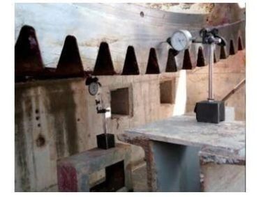
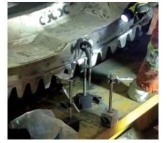
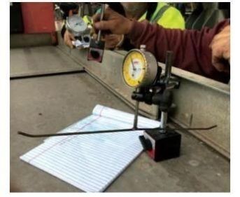
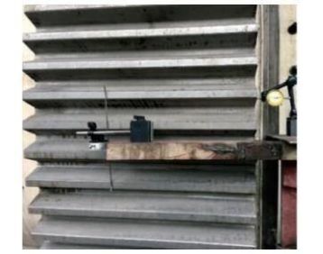
Most on-site dial gauges are installed in Figure 1 or figure 2, both of which have advantages and disadvantages. The position in Figure 1 can directly measure the radial jump at the top of the gear, but a worker is required to press and hold the dial indicator under the gear ring, and release the dial indicator when the tooth to be measured turns around, which is complex to operate and easy to cause injury to workers; the position in Figure 2 is simple to operate, but it is not the real radial jump of the gear. Therefore, we suggest to make a measuring tool (Figure 3) and install it on the head of the dial indicator, so that it is easier to measure the radial jump (Figure 4).
Eight points need to be measured around the ring gear, as shown in Figure 5.
The diameter jump is required to be ≤ 0.25D (unit: m m), and D is the diameter of gear graduation circle (unit: m).
2.3 ring gear end runout
When measuring the end jump, a winch is still needed for disc grinding. Before disc grinding, the sliding shoes or hollow shaft oil station of the mill must be opened, and the floating capacity of the mill shall be checked with a dial indicator. Only when the floating capacity reaches 0.15mm, can the disc grinding be carried out. If the site personnel are sufficient, the end jump and the radial jump can be measured at the same time.
The end run out must be detected by double meter method to eliminate the error caused by the axial movement of the mill. When two dial indicators are installed on the same side of the ring gear, as shown in the left side of Figure 6, calculate the end jump according to line 4 of Table 1; when two dial indicators are installed on both sides of the ring gear, as shown in the right side of Figure 6, calculate the end jump according to line 5 of Table 1. The installation position of the two dial indicators must be 180 ° and 8 points need to be measured around the ring gear, as shown in Figure 5.

03 – Alignment of pinion
After the alignment of the big gear ring is completed, the pinion device shall be put in place according to the requirements of the drawings, the center height of the pinion shall be retested with a level gauge, and the sizing block shall be replaced if necessary to adjust the elevation. Use feeler gauge to roughly find tooth top clearance and tooth side clearance, and install diaphragm coupling, main reducer, auxiliary transmission device and main reducer lubricating oil station.
Grouting the anchor bolts of the pinion device once. After the primary grouting strength reaches 70% of the design strength, use the auxiliary drive plate to grind, and retest the runout of the big gear ring again, and then start the fine alignment of the pinion.
Most of the site is to use feeler gauge and red lead powder to detect the contact condition of the gear. There is no basis for the adjustment of this detection method, so the adjustment amount of the bearing seat can only be determined by experience, which is time-consuming and laborious. Compared with this method, the lead wire method can accurately calculate the amount of each adjustment, which is more accurate and saves installation time.
Before alignment, the lead wire shall be used to make a measuring tool as shown in Figure 7. In the figure, the left tool is used to measure the side gap and the right tool is used to measure the top gap. Set 12 sets of jackscrews at the 1-12 positions of the pinion bearing pedestal, and set 8 dial indicators at the 1-8 positions, as shown in Figure 8.
If there is no error in the processing of large and small gears, the graduation circle shall be tangent during installation, and its top clearance shall be 1 / 4 gear module. Considering the processing error caused by the hob wear and the floating amount of the mill when it is running relative to the static state and other factors, in order to avoid the gnawing back of the gear when it is running, it is recommended to increase the top clearance by 1.5-2.5mm during the installation, which can be adjusted according to the actual situation on site.

See Table 2 for side clearance requirements.
On the basis of meeting the above requirements, the larger the top clearance and side clearance is, the better, and the side clearance deviation on both sides of the gear is not more than 0.1mm, and the top clearance deviation on both sides of the gear is not more than 0.3mm. 8 points are measured in a week, and 5 points meet the requirements.
Refer to figure 5 for the measurement position, and the measurement sequence is:
(1) Measuring points: 1, 3 and 6. If two points meet the requirements, it can continue. Otherwise, it needs to be adjusted and re measured.
(2) Measuring points: 2, 5 and 8. If two more points meet the requirements, it can continue. Otherwise, it needs to be adjusted and re measured.
(3) Measuring points: 4, 7. If another point meets the requirements, the alignment is completed (i.e. at least 5 of the 8 points meet the requirements), otherwise, it is necessary to re measure after adjustment.
When adjusting the top clearance, refer to the reading of 5-8 position dial indicator and adjust 1-4 jacking screws; when adjusting the side clearance, refer to the reading of 1-8 position dial indicator and add or remove the adjusting gasket under the bearing pedestal.
After the lead wire method is used for alignment, the contact condition of the engagement surface of the large and small gears shall be retested with blue or red lead powder. The contact area shall not be less than 40% of the tooth height and 50% of the tooth width, and the contact on both sides of the gear shall be uniform, and only one side contact is not allowed, otherwise further adjustment is required.